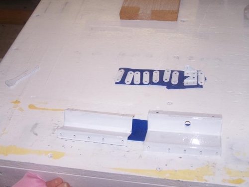
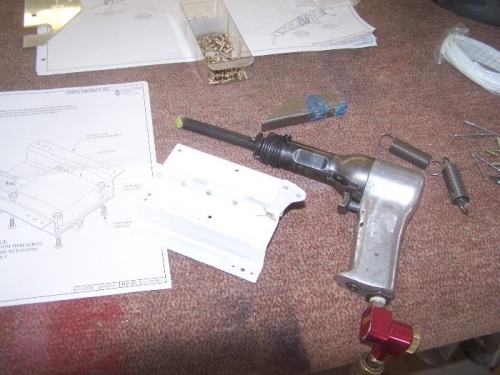
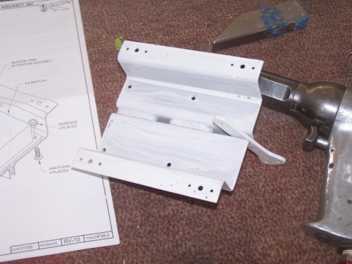
Over the last several weeks I installed the electric aileron trim. I started by separating, drilling and deburring the mounting brackets. Next I separated, drilled and deburred the aileron trim links. Then I primed the parts. When the paint was dry I assembled the trim actuation assembly and riveted it together using the rivets called out on page OP38-2. Next, I prepared the mount by drilling the four screw holes to #28, then I attached the trim servo to the mount using the hardware listed. Finally, I inserted the snap bushing in the mount and ran the wires through it. The next step was to attach the servo mount to the inboard most left wing access plate. I placed the mount on the access plate according to the dimensions shown on page OP38-4. Then I match drilled the 4 5/32" holes in the trim assembly mount to the wing access plate. Then I continued following the steps to attach the nutplates to the servo mount so it could be screwed to the access plate. I debirred everything and dimpled the holes. Next I riveted the nutplates to the servo mount and screwed the mount to the access plate. After confirming that the aileron moves through its full range without interference of the servo arm, I separated, trimmed drilled and deburred the aileron trim spring brackets. With the aileron in the neutral position I marked the center of the aileron trim arm on the aileron pushrod. Next, I removed the pushrod and measured inboard and outboard 6" to position the spring mounts. I match drilled the two holes on each spring mount to the aileron pushrod then riveted the mounts to the pushrod. I attached the springs to the mounts next and reinstalled the pushrod. Next, I attached the servo arm to the springs and finally re-mounted the servo mount to the access plate to finish the job. Note that none of the wiring was ran at this time but earlier in the process I did center the servo by using a 9 volt battery and centering the servo.